Creating an IoT LED matrix controlled by Storyblok
Storyblok is the first headless CMS that works for developers & marketers alike.
What if, instead of doing another Zoom call, we used IoT to connect to our team? What would happen if your remote team could change actual LEDs in your office? This blog post explains how to get started with LEDs & Storyblok. It includes the technical aspects of using Storyblok to control LEDs, as well as implementing a small Svelte component to create a simple interface, that is easy to interact with.
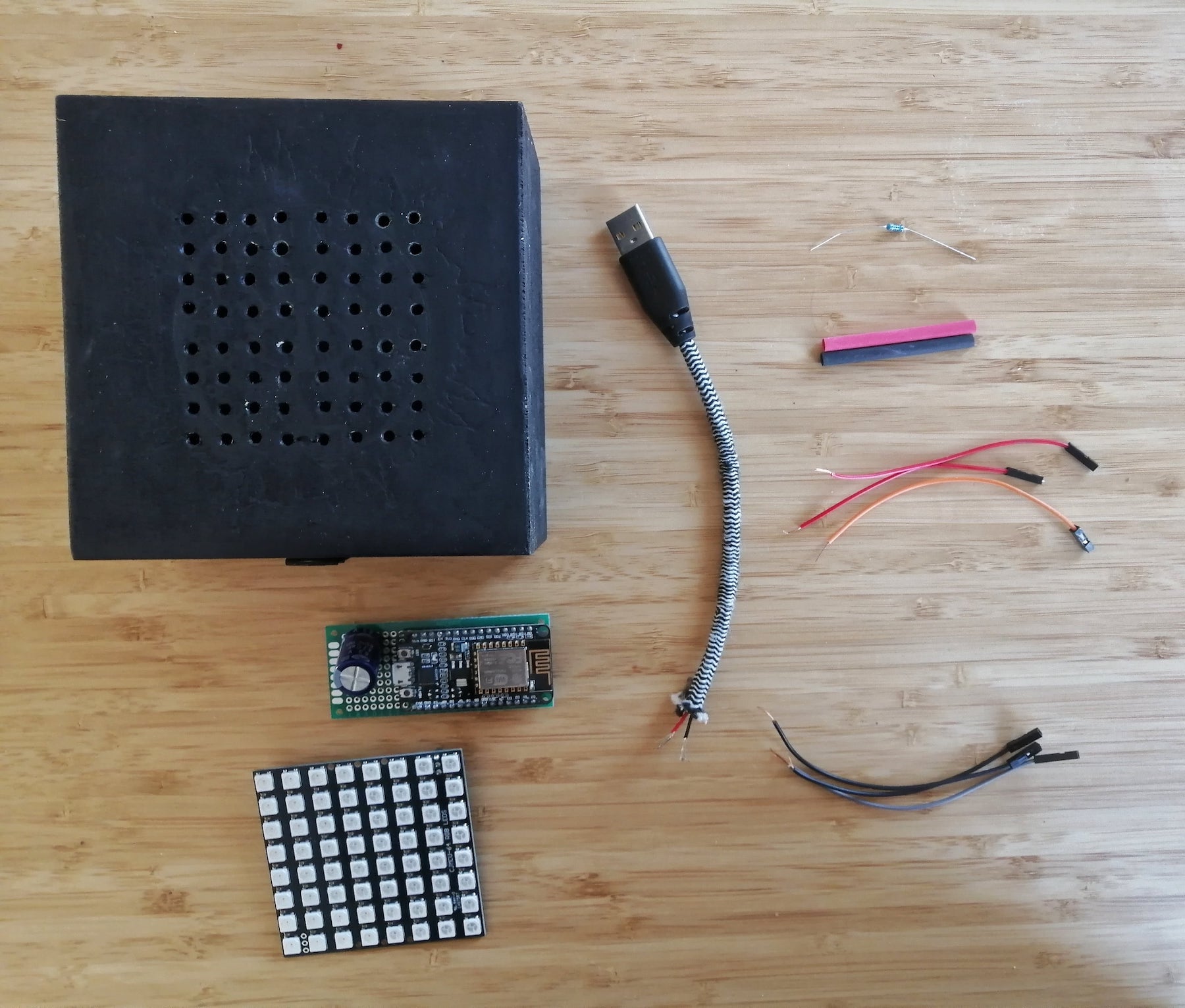
Parts
- ESP8266 wifi microcontroller (e.g. NodeMCU Lolin V3) ~6€
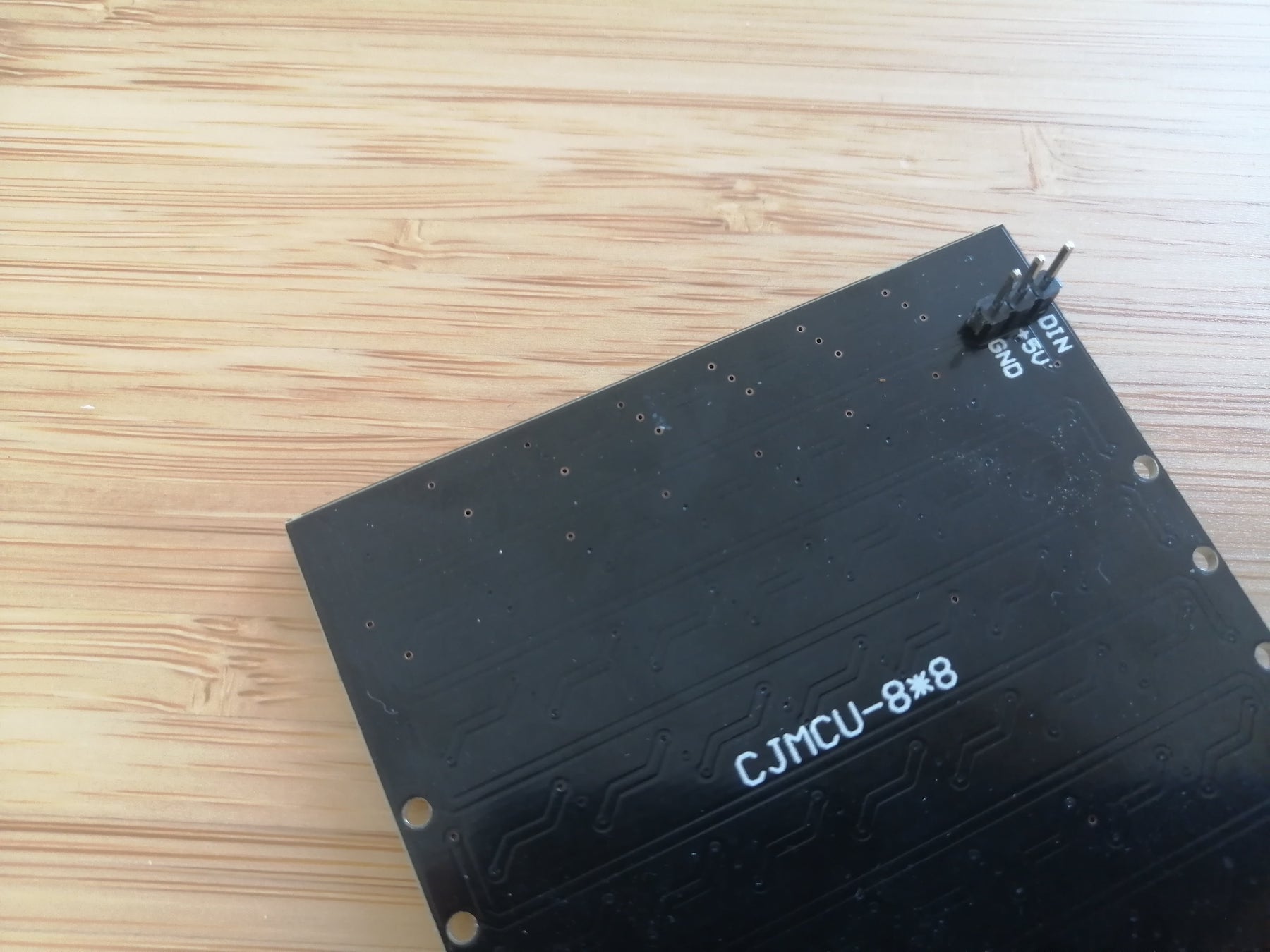
- LED matrix module (e.g. CJMCU-8x8 Modul) ~10€
- Capacitor (1000 µF), ~40cents
- Resistor (470 ohm), ~5cents
- Powerbank + Cable or a Battery, ~5-10€
- Female to female arduino jumper wires ~4€
- Solder Iron, ~12€
Wiring Diagram
Almost any IoT project will include a wiring diagram. The wiring for this project is not too complex:
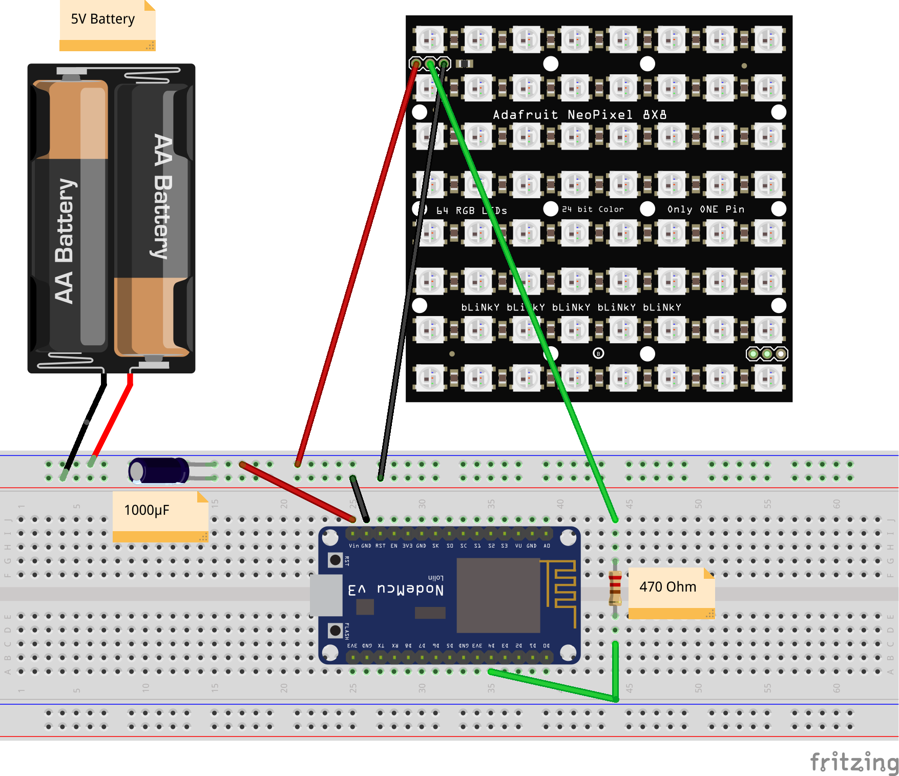
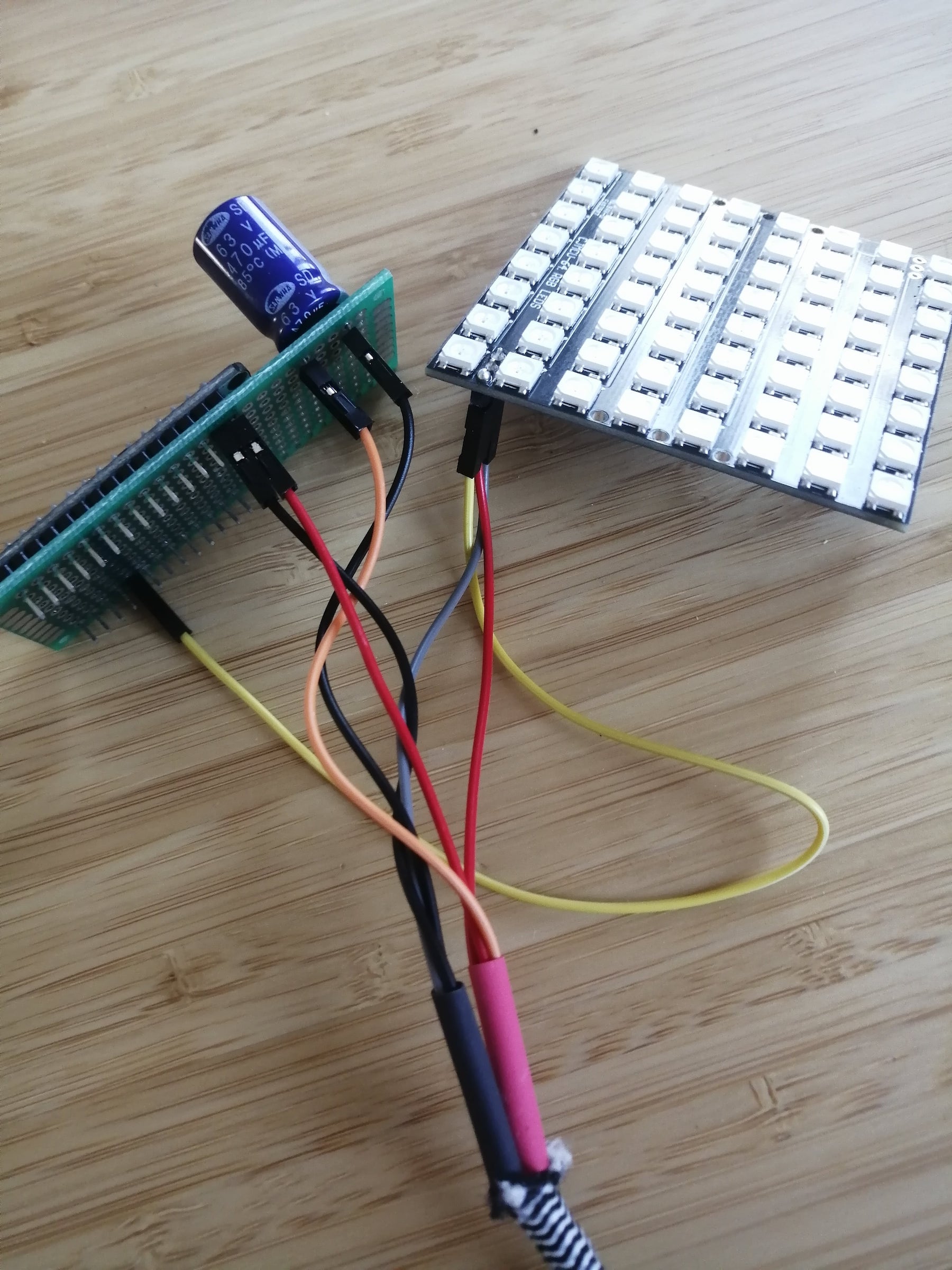
You have the microcontroller (ESP8266) that sends data to the LED matrix (green wire). In between the data line, you should include a small ~470-ohm resistor. Adding a resistor between your microcontroller's data pin and the data input on the LEDs can help prevent spikes on the data line that can damage your first pixel.
Then you have some power source, for example, a power bank or a battery, that can provide 5V. From the power source, you have two ground connections (black wire) to the microcontroller GND pin and the LED matrix GND pin.
You also need a power connection 5V (red wire) to the VIN pin of the microcontroller and the 5V PIN on the LEDs. When working with LEDs it's recommended to have a capacitor (1000 µF) between the GND and 5V connection to protect the LEDs. Before connecting LEDs to any large power source, add a capacitor across the GND and 5V connections. The capacitor buffers sudden changes in the current drawn by the strip.
I can recommend the Adafruit Neopixel Überguide (opens in a new window) to understand the basics of working with LEDs and microcontrollers.
Prototype Kit
The easiest way to get started is to use a breadboard to prototype what you want to do before doing any soldering. I bought a basic kit (~13€) that includes a breadboard, some resistors, buttons and cables to prototype. I still use the breadboard on any project I start, because it allows me to try things out without having to solder anything in the beginning.
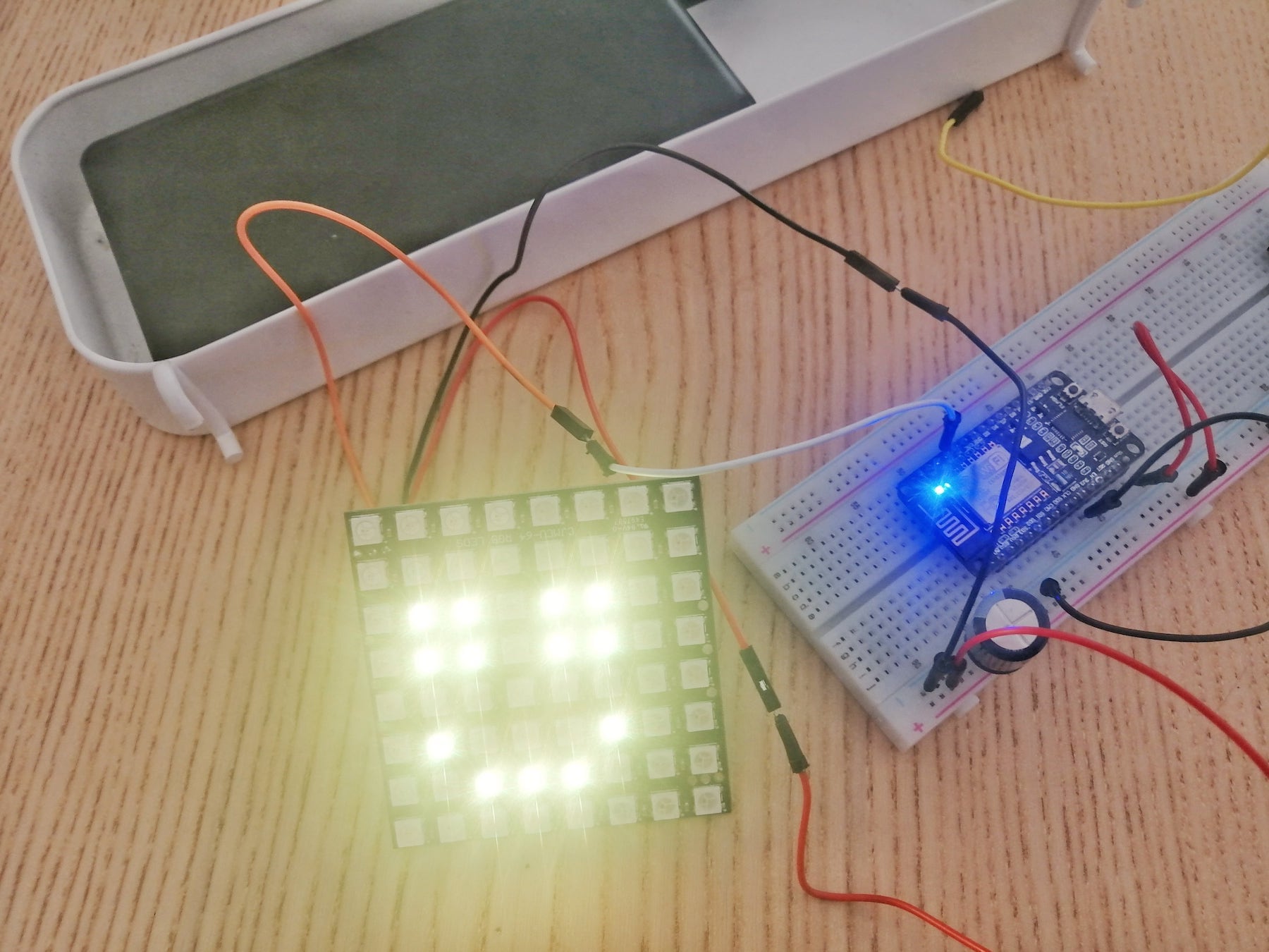
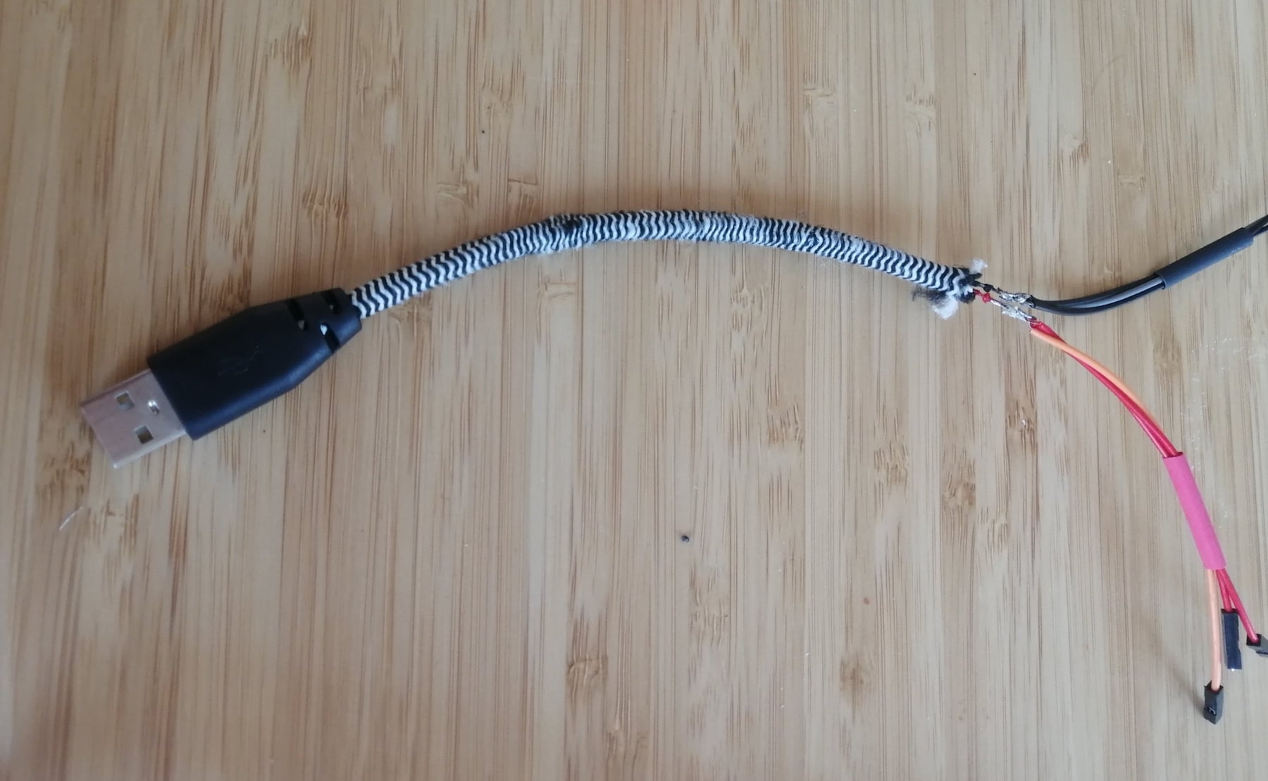
USB Cable
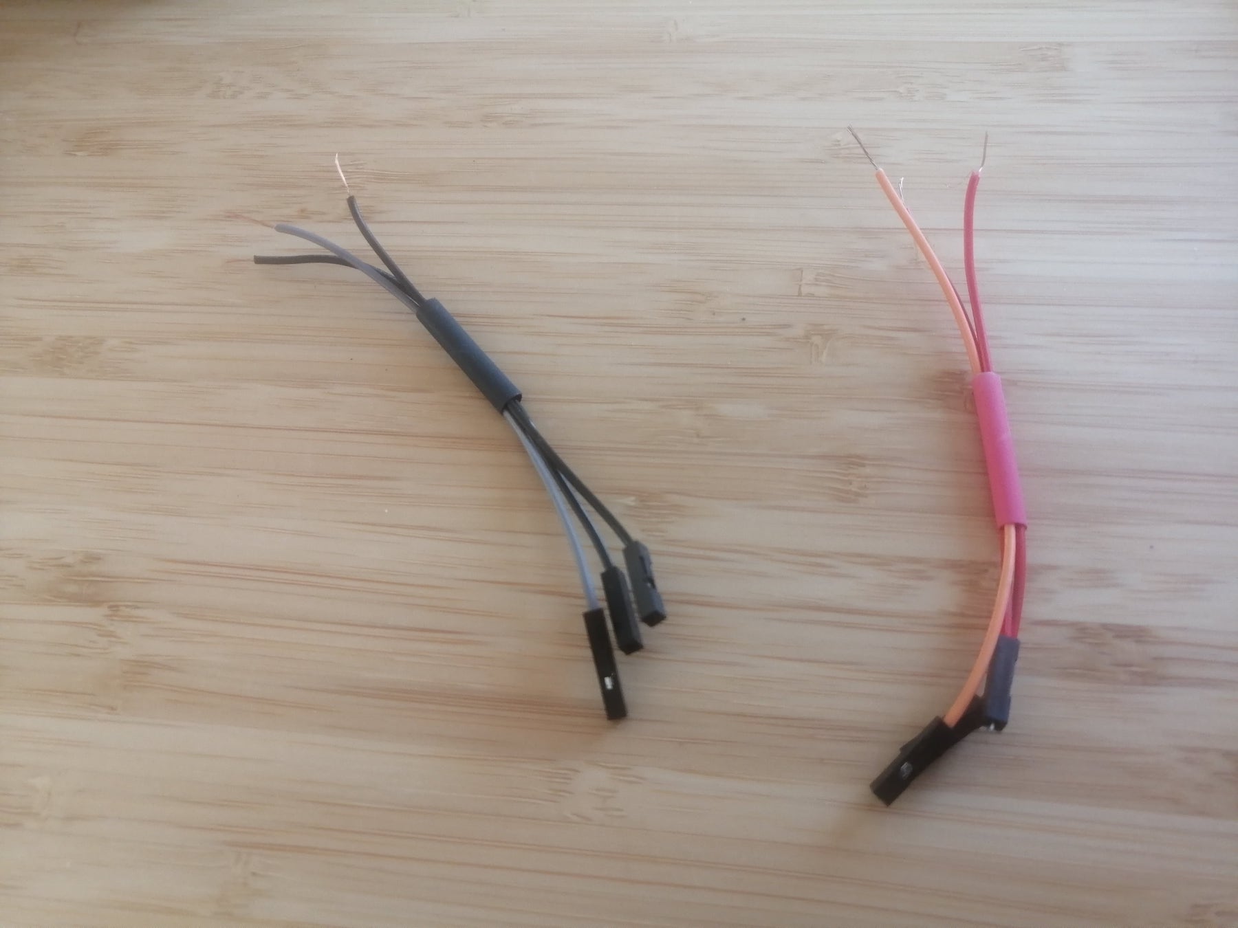
I cut open an Ikea power cable I had lying around and created three power and ground connections from it. Don't forget to add some shrink tubes to the cables, so the GND and VIN connections do not touch each other. I soldered some female jumper wires together and then connected them to the USB cable. There are also some white/green data cables in a USB cable, which I just cut off and ignored. This was all the soldering I had to do.
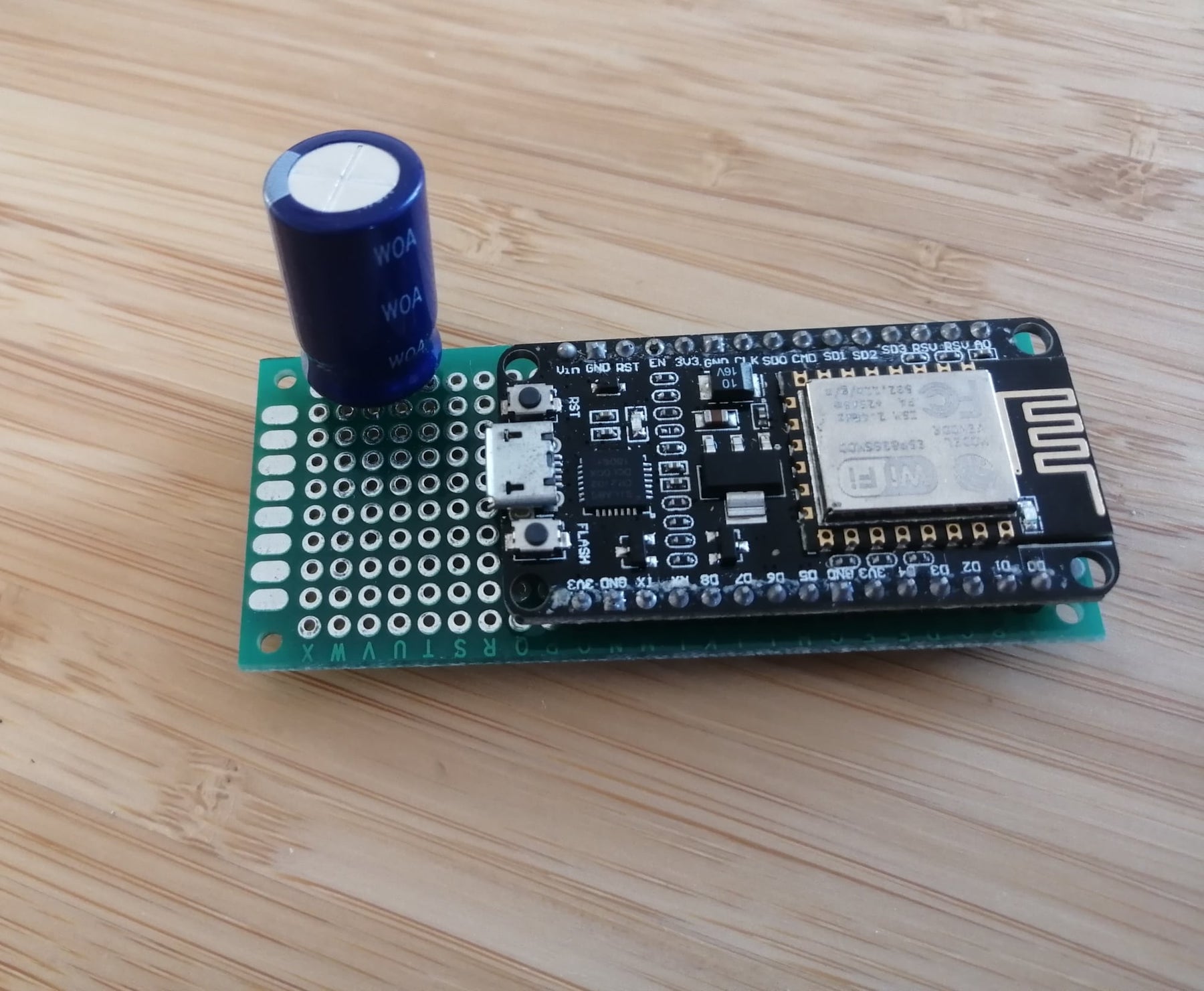
Microcontroller
We have 3 connections that we need on the microcontroller: the GND connection to the USB cable, the VIN connection to the USB Cable and we have the D4 data pin to the LEDs. You can also use any other data pin since you can set which data pin you're using in the code.
LED matrix
The first step for me was to solder the pins on the matrix. We only need the incoming pins, since we're only connecting one matrix. Then we can connect the 5V and GND pin to the USB cable. The data pin needs to be connected to the microcontroller with the 200-470 Ohm resistor in between.
Capacitor
The last missing piece is the capacitor, I added this one on the third ground and 5V connection I created on the USB cable.
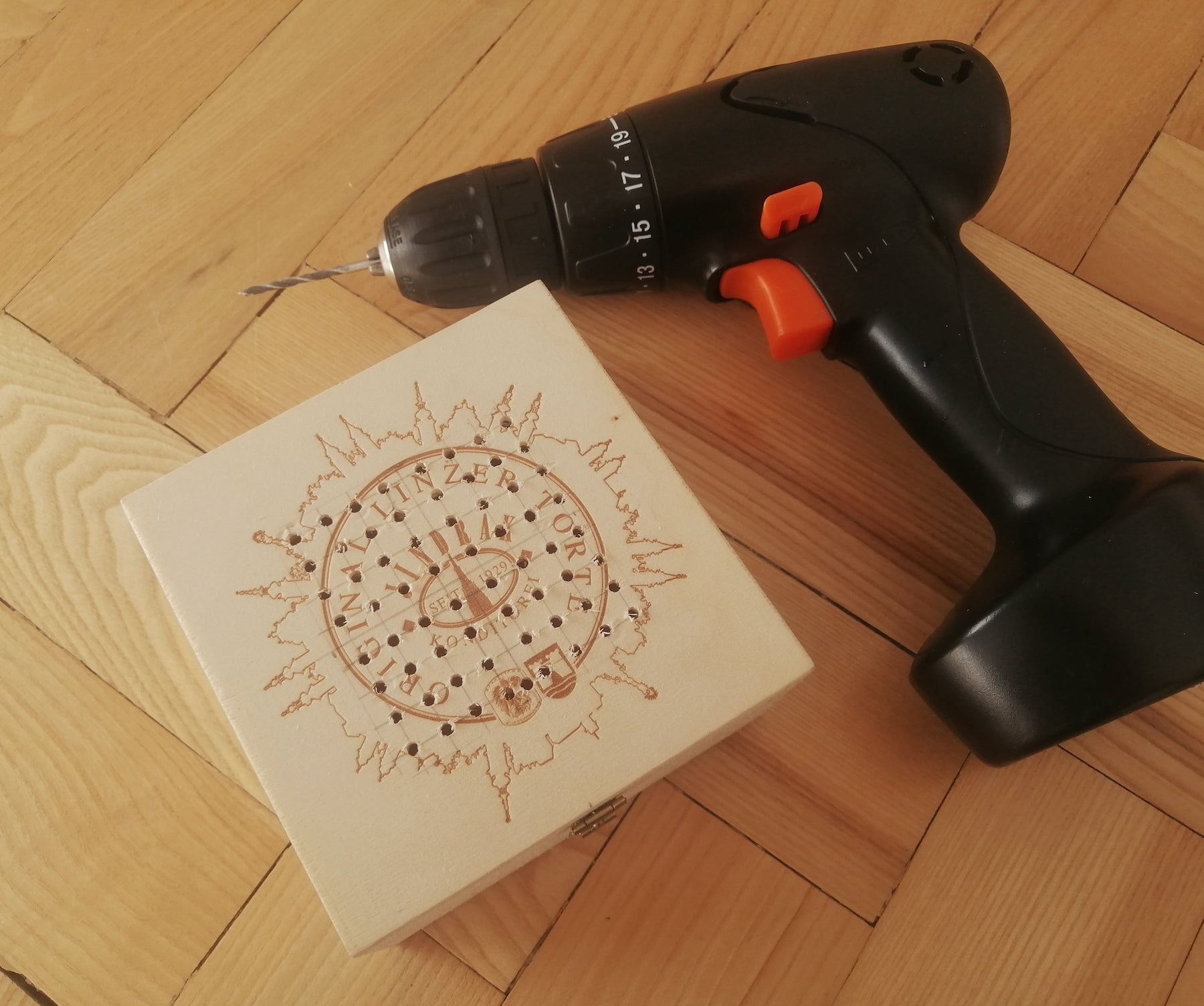
Building the Box
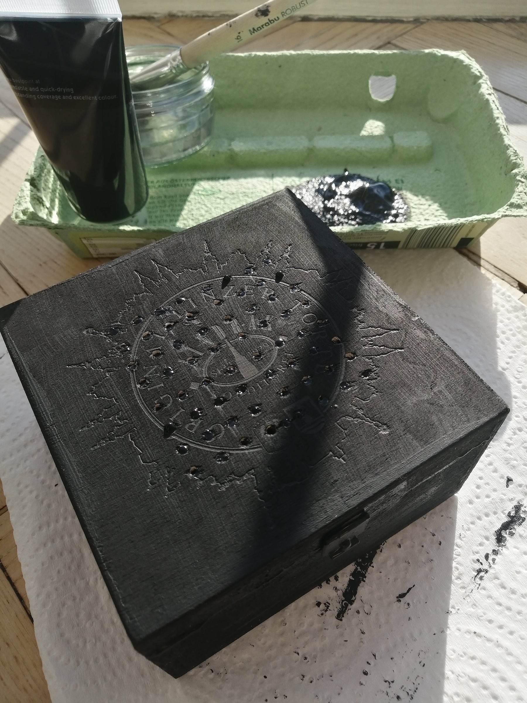
For the box I decided to refurbish a Linzer Torte (opens in a new window) box I had gotten as a present at the ScriptConf (opens in a new window) conference, where I first met Storyblok. I measured the distances from the matrix, drilled some holes and painted the whole box black with acrylic color.
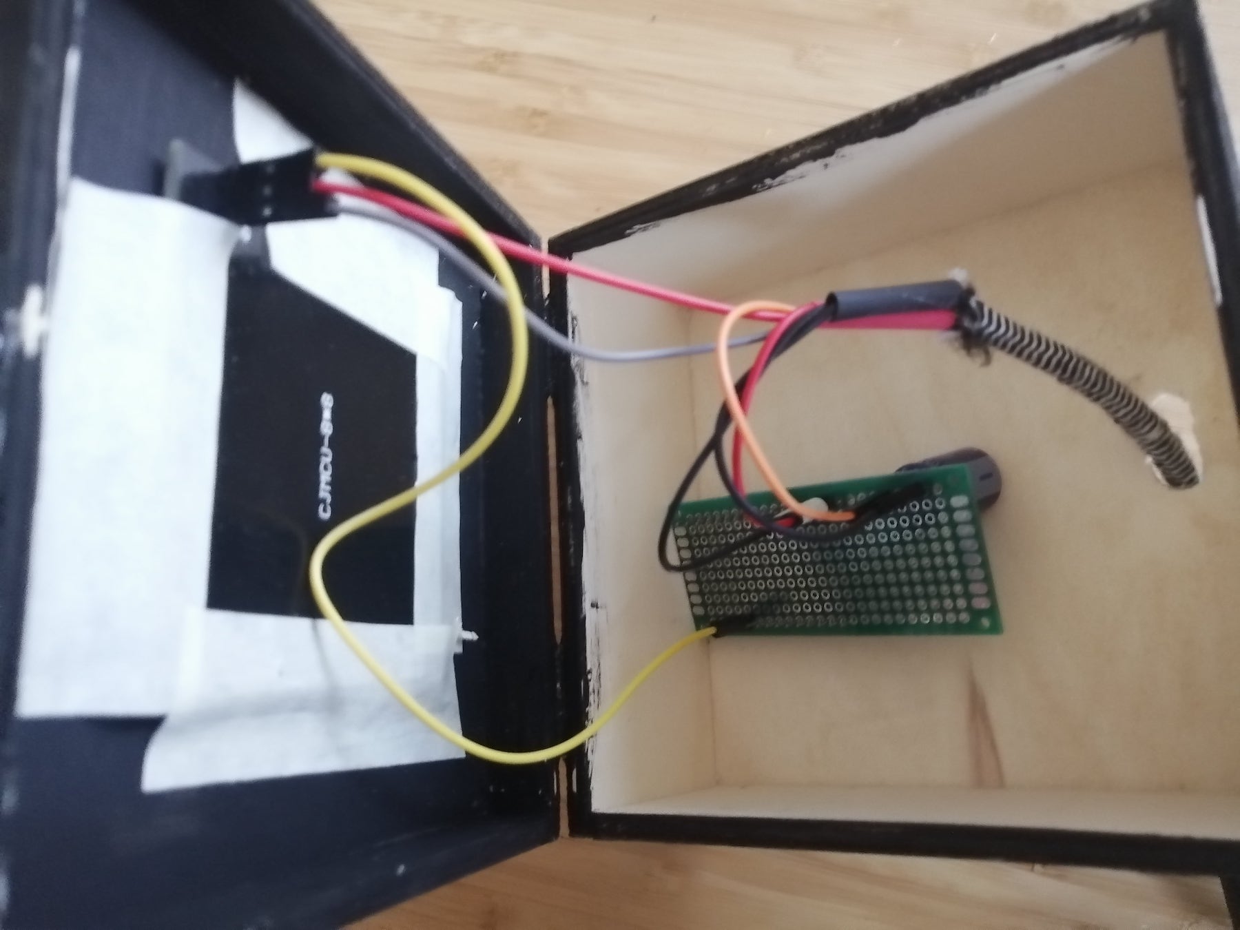
Finally, I attached the matrix to the top of the box with some tape and drilled a hole for the USB power cable in the bank to attach my large power bank. In the future, I want to get a small power bank that fits inside the box.
Code
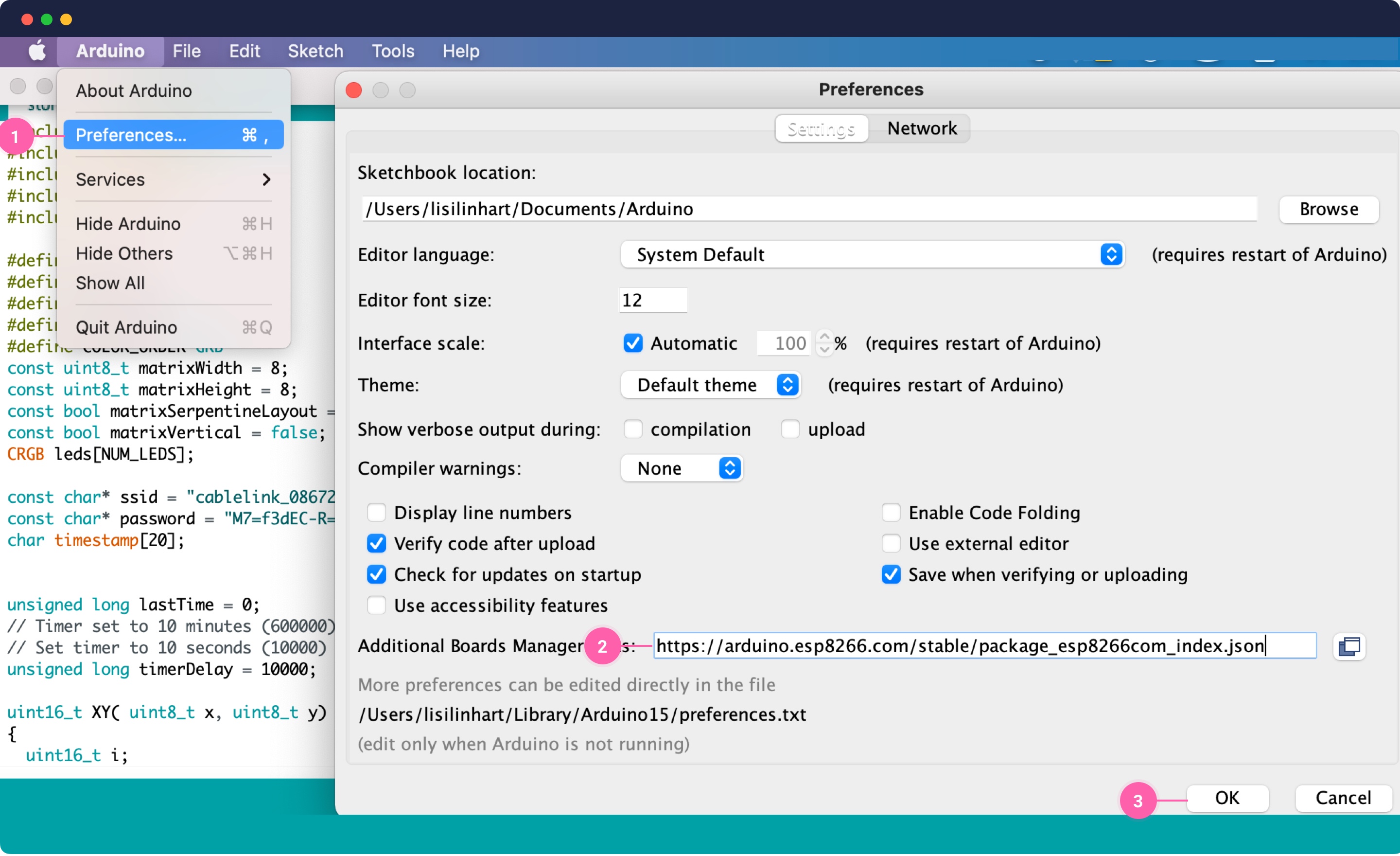
Finally, we need to set up the environment to put our code on the microcontroller. I followed this basic tutorial (opens in a new window) to get the environment running. The first step is to install the Arduino IDE. Next, we need to add the correct board manager: Click on Arduino --> Preferences {1}, and at the bottom under "Additional Board Managers" {2}, enter the manager for your board. For my board it was https://arduino.esp8266.com/stable/package_esp8266com_index.json
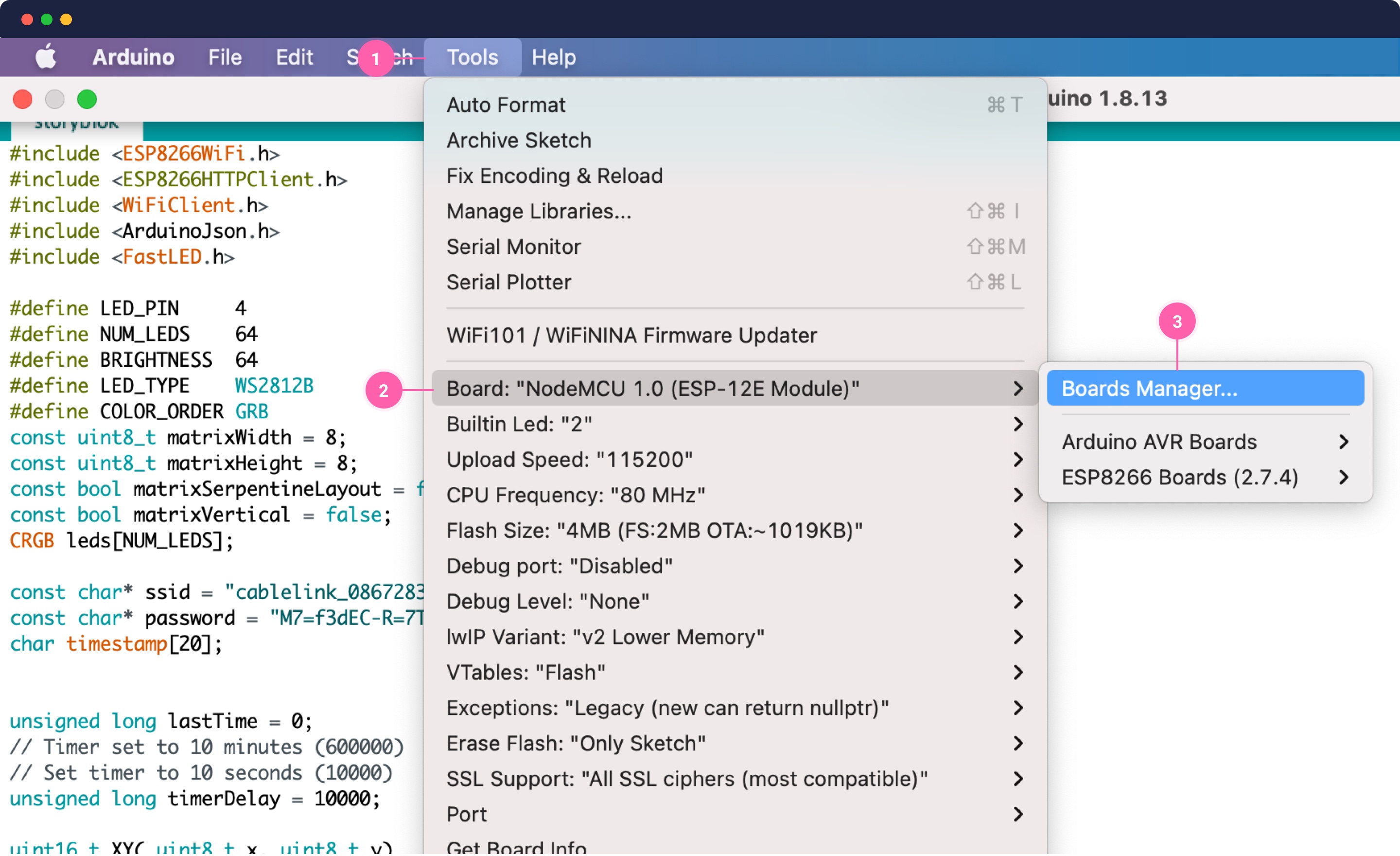
Once you added the manager you need to go to Tools {1} --> Boards {2} --> Boards Manager {3}. Then search esp8266 and install the package, if it's not installed already.
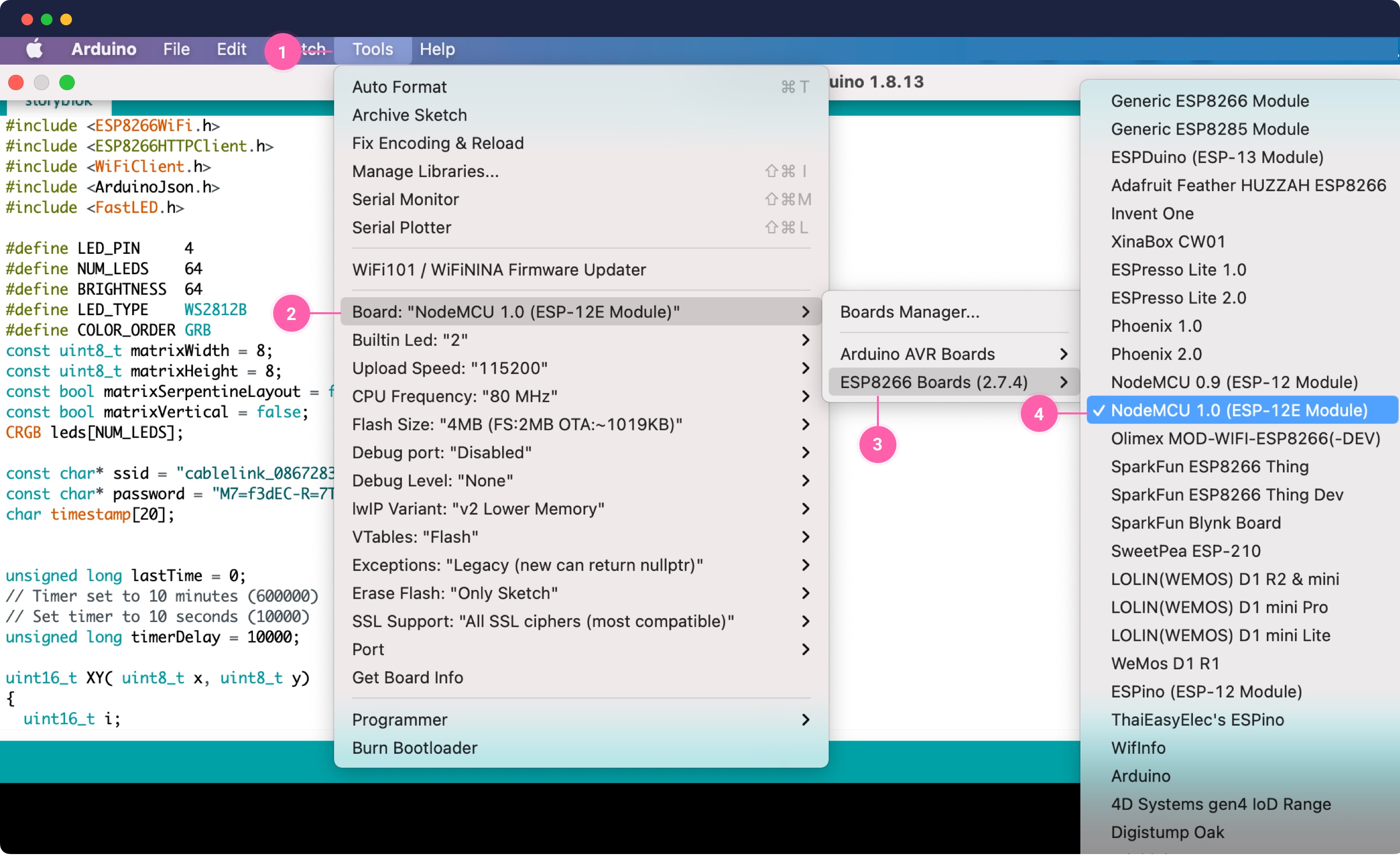
Finally, select the correct board. Go to Tools {1} --> Board {2} --> ESP8266 Boards {3} --> NodeMCU 1.0 {4}
The last setup step is to install the necessary libraries we need. Go to Sketch --> Include Library --> Manage Libraries and install the following libraries: ESP8266WiFi , ESP8266HTTPClient , WiFiClient, ArduinoJson, and FastLED.
Let's add the different parts of our code, first we need to include all the libraries:
#include <ESP8266WiFi.h>
#include <ESP8266HTTPClient.h>
#include <WiFiClient.h>
#include <ArduinoJson.h>
#include <FastLED.h>
Then we need to define some basic variables, the LED_PIN is the number of our microcontroller data pin. We have an 8x8 matrix, so 64 LEDs. We're setting a fixed LED brightness of 64. Our LED type is a WS2812B, which is a very common type of LED. And the color order needs to be set according to the module you're using, for me it's CRB. Since our ESP8266 has a wifi module, we also need the settings of the wifi to connect to. Here is a basic example (opens in a new window) of how Wifi connections of the ESP8266 work.
#define LED_PIN     4
#define NUM_LEDS    64
#define BRIGHTNESS  64
#define LED_TYPE    WS2812B
#define COLOR_ORDER GRB

// wifi settings
const char* ssid = "wifi-name";
const char* password = "wifi-password";

// updating timer
char timestamp[20];
unsigned long lastTime = 0;
unsigned long timerDelay = 10000; // Set timer to 10 seconds (10000)
Next we have some variables for calculating the matrix layout and the settings of the wifi to connect to. The calculations and variables I copied from the FastLed XY Matrix example (opens in a new window). It allows you to calculate the x and y values of each pixel depending on the layout of the matrix.
// matrix layout
const uint8_t matrixWidth = 8;
const uint8_t matrixHeight = 8;
const bool matrixSerpentineLayout = false;
const bool matrixVertical = false;
CRGB leds[NUM_LEDS];

uint16_t XY( uint8_t x, uint8_t y)
{
  uint16_t i;

  if( matrixSerpentineLayout == false) {
    if (matrixVertical == false) {
      i = (y * matrixWidth) + x;
    } else {
      i = matrixHeight * (matrixWidth - (x+1))+y;
    }
  }

  if( matrixSerpentineLayout == true) {
    if (matrixVertical == false) {
      if( y & 0x01) {
        uint8_t reverseX = (matrixWidth - 1) - x;
        i = (y * matrixWidth) + reverseX;
      } else {
        i = (y * matrixWidth) + x;
      }
    } else {
      if ( x & 0x01) {
        i = matrixHeight * (matrixWidth - (x+1))+y;
      } else {
        i = matrixHeight * (matrixWidth - x) - (y+1);
      }
    }
  }

  return i;
}
The main parts of every Arduino project are the setup (opens in a new window) and the loop (opens in a new window) function. The setup function is the function that is called once, when the microcontroller is powering up. Here we set a short delay while it's powering up. Set the port for the Serial monitor to debug our code Serial.begin(115200). Read this tutorial (opens in a new window) to learn how Serial communication works. Basically we need to set the same baud rate in our Arduino IDE and on the controller to be able to display the Serial text. Finally, in the setup, we add our LED settings like the number of LEDs and the brightness and start our Wifi connection.
void setup() {
  delay( 3000 ); // power-up safety delay
  Serial.begin(115200);
  // LED SETUP
  FastLED.addLeds<LED_TYPE, LED_PIN, COLOR_ORDER>(leds, NUM_LEDS).setCorrection( TypicalLEDStrip );
  FastLED.setBrightness(  BRIGHTNESS );
  // Wifi SETUP
  WiFi.begin(ssid, password);
  Serial.println("Connecting");
  while(WiFi.status() != WL_CONNECTED) {
    delay(500);
    Serial.print(".");
  }
  Serial.println("");
  Serial.print("Connected to WiFi network with IP Address: ");
  Serial.println(WiFi.localIP());

  Serial.println("Timer set to 10 seconds, it will take 10 seconds before publishing the first reading.");
}
Finally, after the setup, we have the main loop function, which loops consecutively, allowing your program to change and respond. We're using a lastTime variable to throttle our behavior to only happen every 10 seconds. Once our Wifi is connected, we're creating an HTTP client, which then reads Storyblok's JSON endpoint. If the request was successful, we pass the response to the ArduinoJson (opens in a new window) library, which makes it easy to work with JSON on the microcontroller. They have a nice example of how to work with HTTP requests (opens in a new window).
Once we parsed our response from Storyblok, we will iterate over all the elements in the story.content.body and read the color property, which will be a String hex code. We will then calculate the x and y value of the pixel on the matrix and pass that to a helper function together with the hex string we received from Storyblok colorLEDwithHex(x, y, hexCode).
void loop() {
  //Send an HTTP POST request every 10 seconds
  if ((millis() - lastTime) > timerDelay) {
    //Check WiFi connection status
    if(WiFi.status()== WL_CONNECTED){
       HTTPClient http;
       http.useHTTP10(true);
       http.begin("http://api.storyblok.com/v1/cdn/stories/home?token=your-preview-token&version=draft");
       int httpCode = http.GET();


      if (httpCode > 0) {
        Serial.print("HTTP Response code: ");
        Serial.println(httpCode);
        // https://arduinojson.org/v6/assistant/
        DynamicJsonDocument doc(32768);
        deserializeJson(doc, http.getStream());

        for(int i = 0; i < NUM_LEDS; i++) {
           String hexCode = doc["story"]["content"]["body"][i]["color"]["color"];
           uint8_t y = i / matrixWidth;
           uint8_t x = i % matrixWidth;

           if(pixel && pixel.charAt(0) == '#') {
              colorLEDwithHex(x, y, hexCode);
           }
        }

        FastLED.show();
      }
      else {
        Serial.print("Error code: ");
        Serial.println(httpCode);
      }
      // Free resources
      http.end();
    }
    else {
      Serial.println("WiFi Disconnected");
    }
    lastTime = millis();
  }
}
The last part is our helper function, it takes the x and y values and the hex code. This function calculates r, g, b values out of the hex code and sets the color directly on the correct pixel by using our XY() helper function.
void colorLEDwithHex(uint8_t x, uint8_t y, String hexCode)
{
    byte r,g,b;
    long number = (long) strtol( &hexCode[1], NULL, 16);
    r = number >> 16;
    g = number >> 8 & 0xFF;
    b = number & 0xFF;

    CRGB color = CRGB(r, g, b);
    leds[ XY(x, y)] = color;
}
And that's all the code we need on our microcontroller to color the LEDs.
Storyblok Setup
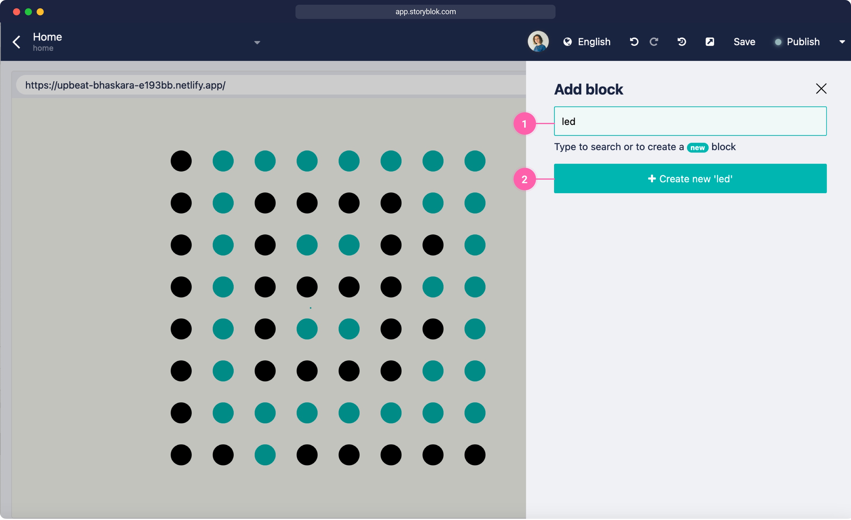
Of course, we still need our Storyblok setup to control the pixels. Create a new space, click on Content and open the Home story. There you should already have a body field of the type blocks set up. Click on the body, delete the teaser and grid and click Add block. Enter led {1} as a name and click Create new 'led' {2}.
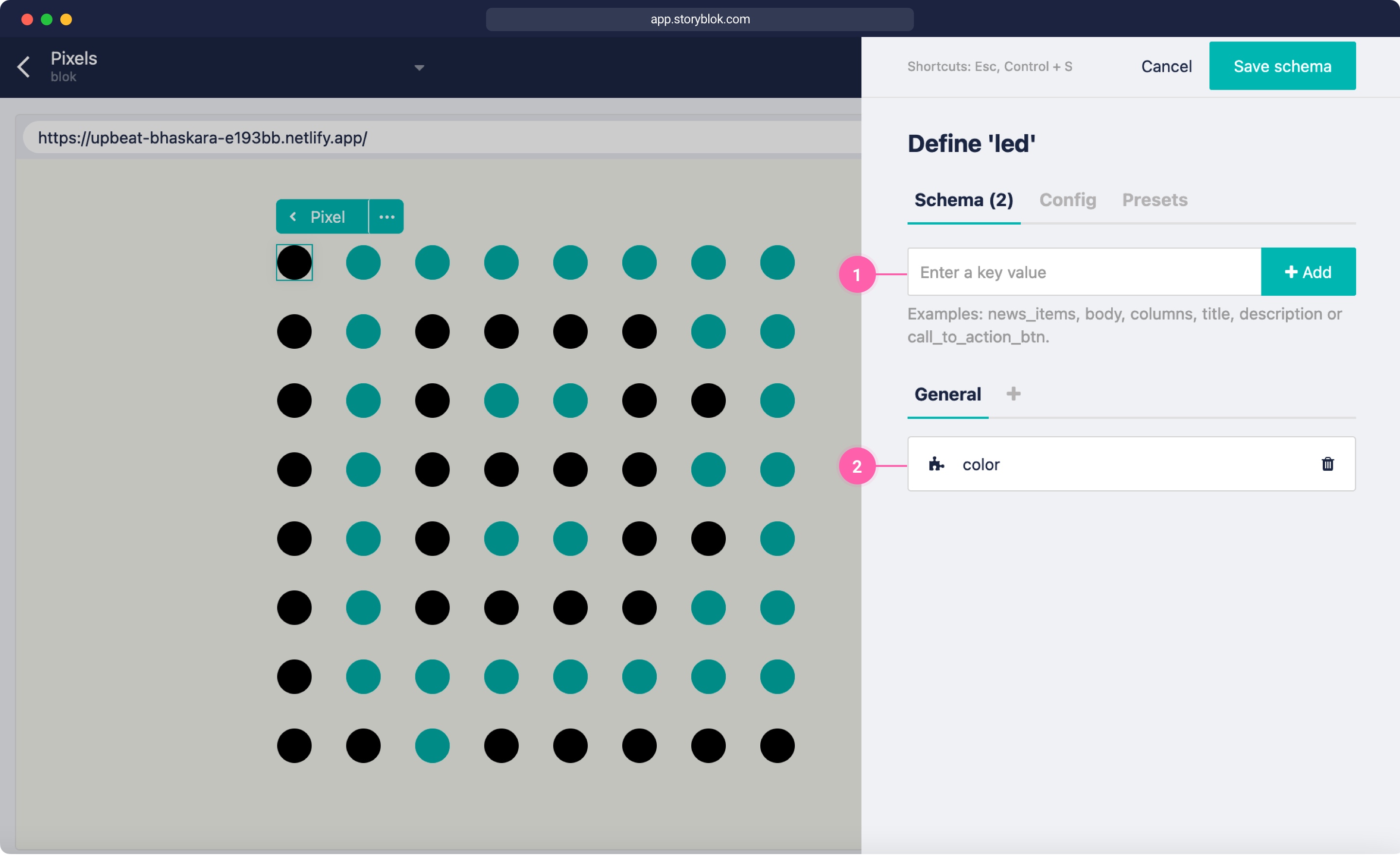
Then for the led enter a new value {1} named color. Click on the new value {2} and as a Type, select Plugin. Then as a custom type select native-color-picker. Now click Save schema.
Finally, if you return to the base page entry, you should be able to add multiple LED blocks to the body {1}. For my matrix, I had to add 64 LEDs and I sent them all to #000, so initially, they are not colored. To make that easier, I created about 5 and then just copy and pasted multiple blocks.
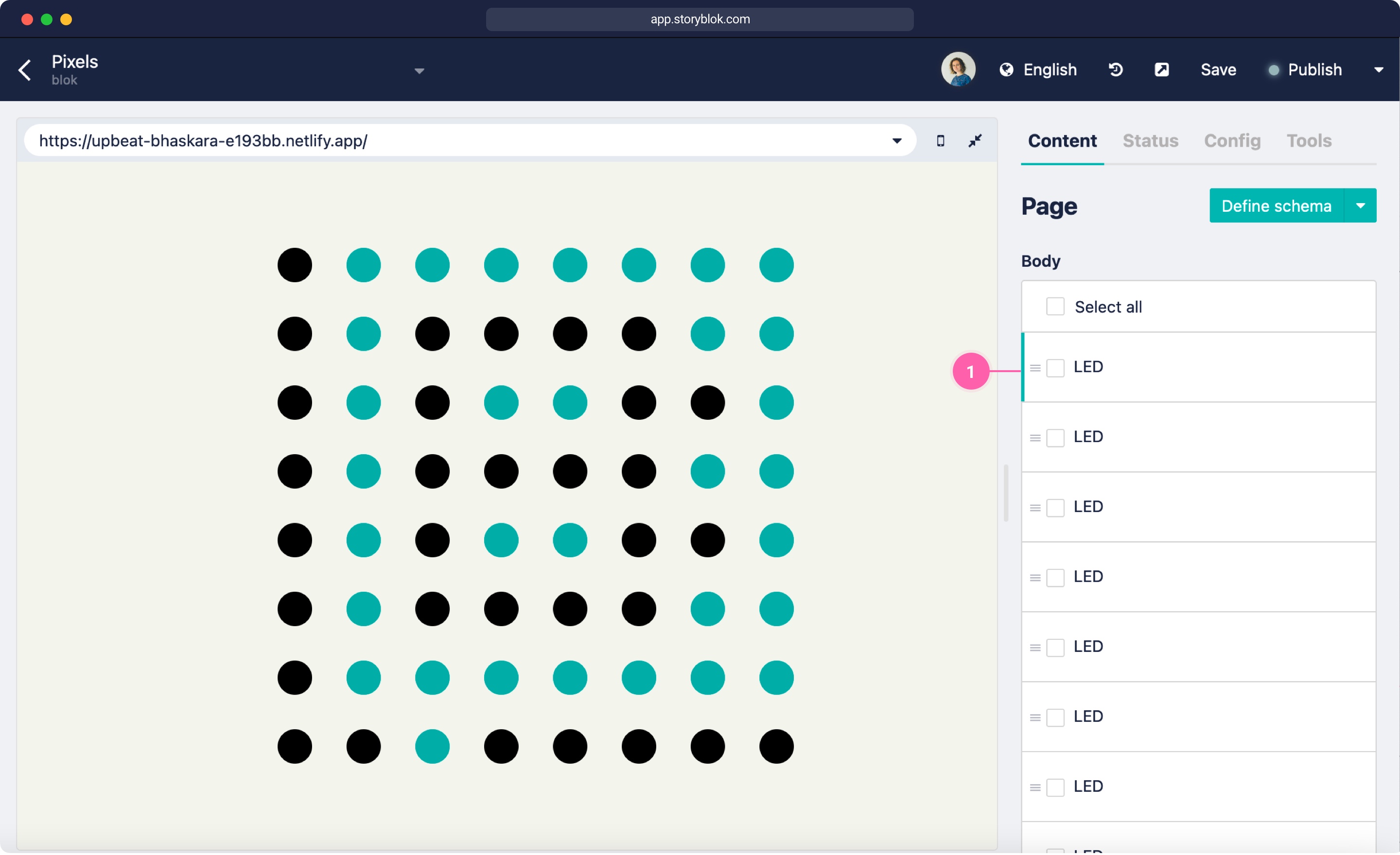
You can also restrict the blocks on the body to only allow led components to be added by clicking Allow only specific components to be inserted on the body schema and selecting the LED component.
Frontend Interface with Svelte
To make this easier to interact with and to understand for my team, who didn't see the LED box live, I create a Svelte component. The component allowed you to select each pixel individually and showed all the current colors. I haven't worked with Svelte before but followed our 5-minute Svelte (opens in a new window) tutorial to set up the connection. I created a file storyblok.js with the following four functions:
const addClass = function (el, className) {
  if (el.classList) {
    el.classList.add(className)
  } else if (!new RegExp('\\b' + className + '\\b').test(el.className)) {
    el.className += ' ' + className
  }
}

export const editable = (el, content) => {
  if (typeof content._editable === 'undefined') {
    return
  }

  const options = JSON.parse(content._editable.replace('<!--#storyblok#', '').replace('-->', ''))

  el.setAttribute('data-blok-c', JSON.stringify(options))
  el.setAttribute('data-blok-uid', options.id + '-' + options.uid)

  addClass(el, 'storyblok__outline')
}
The addClass function adds a storyblok storyblok__outline, the editable function adds the necessary data attributes data-blok-c and data-blok-uid, so Storyblok visual editor can map the DOM nodes to the Storyblok blocks.
export function loadStoryblokBridge (cb) {
  const script = document.createElement('script')
  script.type = 'text/javascript'
  script.src = '//app.storyblok.com/f/storyblok-v2-latest.js'
  script.onload = cb
  document.getElementsByTagName('head')[0].appendChild(script)
}
The loadStoryblokBridge adds a script tag at the end of the bridge and calls a callback once the bridge is loaded.
export function initStoryblokEvents (story, callback) {
  // eslint-disable-next-line no-undef
  const sb = new StoryblokBridge({
    accessToken: '02Qbq8v7brt4VGzcK7BYCAtt'
  })

  sb.on(['change', 'published'], (payload) => {
    callback()
  })

  sb.on('input', (payload) => {
    if (story && payload.story.id === story.id) {
      payload.story.content = sb.addComments(
        payload.story.content,
        payload.story.id
      )
      story = payload.story || {}
    }
  })
}
The initStoryblokEvents function initializes the Storyblok Bridge with your access token and calls a callback once you click Save inside Storyblok. The input function changes the story object that is passed.
App.svelte
The last missing piece is the actual Svelte component. Let's start by adding the Javascript:
<script>
  import { onMount } from 'svelte'
  import { loadStoryblokBridge, initStoryblokEvents, editable } from './storyblok'

  let pixels = []
  let showNames = true

  async function loadStory() {
    const res = await fetch(
      `https://api.storyblok.com/v1/cdn/stories/blok?version=draft&token=your-preview-token`
    )
    const data = await res.json()
    return data.story || {}
  }

  function setPixels(storyEl) {
    if(storyEl.content) {
      pixels = storyEl.content.body
      showNames = storyEl.content.show_names
    }
  }

  onMount(async () => {
    const story = await loadStory()
    setPixels(story)

    const reloadFn = async () => {
      const newStory = await loadStory()
      setPixels(newStory)
    }

    loadStoryblokBridge(() => initStoryblokEvents(story, reloadFn))
  })
</script>
In the onMount function, we're first loading our Storyblok story to get all the pixel value. We're then setting the pixels variables with the values of our story object. Finally, we're loading the Storyblok bridge and after that is loaded, adding our save events. We're also adding a reloadFn, that reloads our Story to display the updated colors once we click save.
<div class="pixels">
  {#each pixels as pixel}
    <figure
      use:editable={pixel}
      class="pixel"
      style="background-color:{pixel.color.color};"
    ></figure>
  {:else}
    <p>loading...</p>
  {/each}
</div>
For the HTML we'll display each pixel as a figure and add the editable directive. We're adding the data from Storyblok directly as inline-style here.
<style>
  .pixels {
    max-width: 400px;
    width: 100%;
    margin: auto;
    display: grid;
    grid-template-columns: repeat(8, 1fr);
    grid-gap: 30px;
  }

  .pixel {
    width: 30px;
    height: 30px;
    border-radius: 100%;
    margin: 0;
    position: relative;
  }

  .pixel__name {
    font-size: 10px;
    position: absolute;
    top: 100%;
    left: 50%;
    transform: translateX(-50%);
    font-family: monospace;
  }

  :global(body) {
    background-color: #f3f4ed;
    display: flex;
    justify-content: center;
    align-items: center;
    min-height: 100vh;
  }
</style>
The CSS to display each pixel similar to the actual physical matrix.
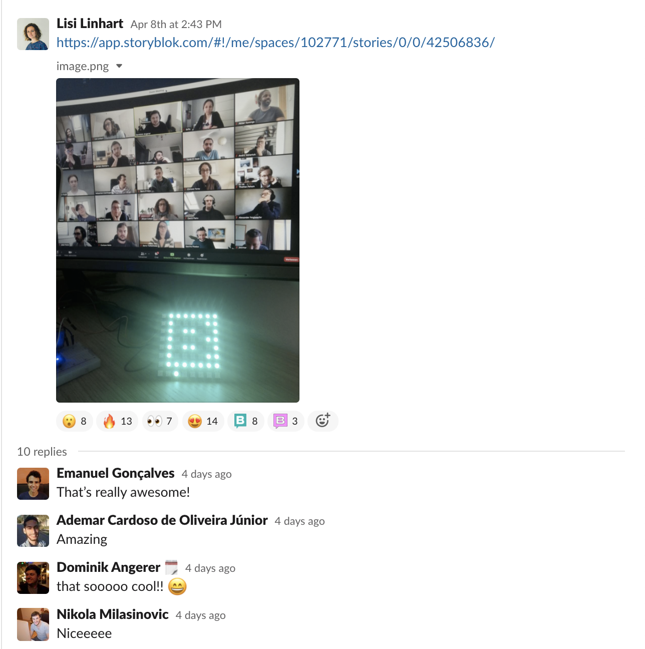
Sharing it with my team
After I had a running prototype, I sent the link to the Storyblok space to my team and let them interact with it. A lot of my team members were excited about the idea and tried it out.
Conclusion
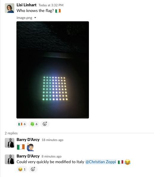
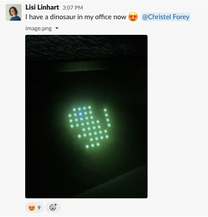
This project was really fun to build and it created some great interactions in my team, so I can totally recommend trying it out! I also learned a lot about using a headless system together with Arduino, which went pretty smoothly in my opinion. Here is a final video of what it looks like.
| Resource | Link |
|---|---|
| Adafruit Neopixel Überguide | https://learn.adafruit.com/adafruit-neopixel-uberguide |
| Arduino IDE | https://www.arduino.cc/en/software/ |
| Arduino JSON | https://arduinojson.org/ |
| Svelte | https://svelte.dev/ |
Question or Feedback?
Author
